
Case Studies
Virtual Pre-Production for Netflix's Monster: The Lizzie Borden Story.
Reality capture let Netflix's Monster scout 35 Italian locations in four days with PortalCam, then plan shots remotely through virtual scouting of 3DGS scans.
By replacing traditional manual methods, XGRIDS enables faster, more precise floor plan creation, enhancing decision-making in property management.
Intro: In this case study, we explore how XGRIDS' advanced SLAM (Simultaneous Localization and Mapping) technology and handheld 3D LiDAR scanners, such as the Lixel L2, have transformed the efficiency and accuracy of real estate surveying and mapping. By replacing traditional manual methods, XGRIDS enables faster, more precise floor plan creation, enhancing decision-making in property management.
Traditional surveying and mapping methods, such as manual surveying, are inefficient and prone to errors when facing large-scale and complex real estate surveying and mapping tasks. However, the emergence of SLAM technology has brought unprecedented changes to the drawing of real estate floor plans. This technology, with its efficient and accurate characteristics, is gradually replacing traditional surveying and mapping methods and becoming the new favorite in the field of real estate surveying and mapping.
This article will delve into the application of SLAM technology in real estate floor plan drawing and how it leads real estate surveying and mapping towards a more intelligent and automated future.
Client Name and Industry:
The client is a prominent real estate development firm engaged in residential and commercial property projects, specializing in building and land surveying for urban development.
Challenge/Problem:
The client faced significant challenges in gathering accurate real estate data, including inefficient manual measurement methods, limited detail capture, and time-consuming data processing, which impacted overall project timelines and decision-making accuracy.
Real estate surveying and mapping mainly measures the natural condition, ownership status, location, quantity, quality, and utilization status of houses and related land. The surveying and mapping content is rich and diverse, including land use survey, house survey, control survey, real estate element measurement, real estate framing drawing, real estate dome drawing, house layered and household floor plan drawing, as well as house area prediction and measurement of building area.
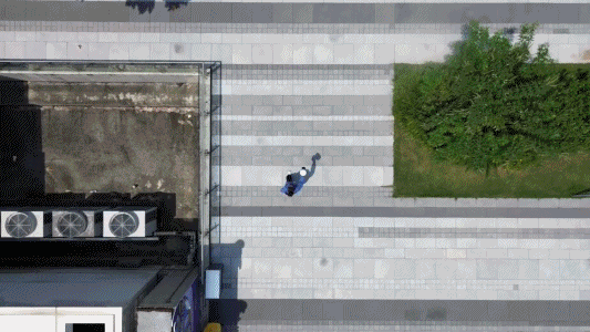
However, traditional real estate surveying and mapping methods mainly rely on manual measurement, such as using tools such as Laser Range Finder and ruler. This method is particularly difficult when facing large-scale real estate surveying and mapping tasks (such as a building or a community), not only inefficient, but also prone to errors. In addition, manual measurement is also difficult to accurately capture the indoor structure and complex details of the real estate property, resulting in inaccurate and comprehensive surveying results. In order to solve the shortcomings of traditional measurement methods, SLAM technology has emerged, bringing a new solution to real estate surveying and mapping.
Technologies/Products Used:
SLAM (Simultaneous Localization and Mapping) technology, also known as simultaneous localization and mapping technology, is a technology that estimates device self-positioning and constructs environmental maps in real-time through sensor data. In the drawing of real estate floor plans, SLAM technology can quickly and accurately scanning for indoor spatial data of the house through a handheld 3D LiDAR scanner, and generate a point cloud model in real-time, greatly improving the CAD drawing efficiency and accuracy.
The Lixel L2 Pro handheld 3D scanner has quickly become a new favorite in the field of real estate surveying and mapping due to its small size, light weight, easy portability and operation. Lixel L2 Pro adopts LiDAR + visual Multi-SLAM method to achieve scanning while moving, with a scanning speed of up to 320,000 or 640,000 points per second, greatly shortening data acquisition time and improving field work efficiency. Real-time postback and preview of data, real-time generation of point cloud models, greatly improving the efficiency and accuracy of real estate floor plan drawing.
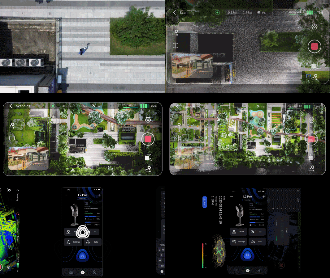
Taking the indoor scanning of the building as an example, technicians use the Lixel L2 handheld 3D scanner to scan according to the planned path and draw the floor plan of the property.
After understanding the customer's project needs, it is necessary to plan the scanning route in advance. It is recommended to work alone or reduce the number of followers during collection to reduce the shadow noise in Point Cloud. The specific operation process mainly includes preliminary survey, route planning, on-site scanning, data preprocessing, data post-processing, and result floor plan drawing.
The Lixel L2 scanner was deployed on-site, and the technician used it to scan the housing property, following a planned path. The scanning process only took a few minutes per room and balcony. The collected data was immediately processed into high-quality point cloud models using LCC Studio software. The post-processing time was approximately 1.5 hours, and the final results were instantly available for visualization and decision-making.

(1) Hold the device correctly:
When scanning, hold the scanning device normally, keep your hands stable, a certain distance from your chest, and avoid swinging greatly or placing the device horizontally. (Especially when carrying the RTK module, it will affect the reception of RTK signals)
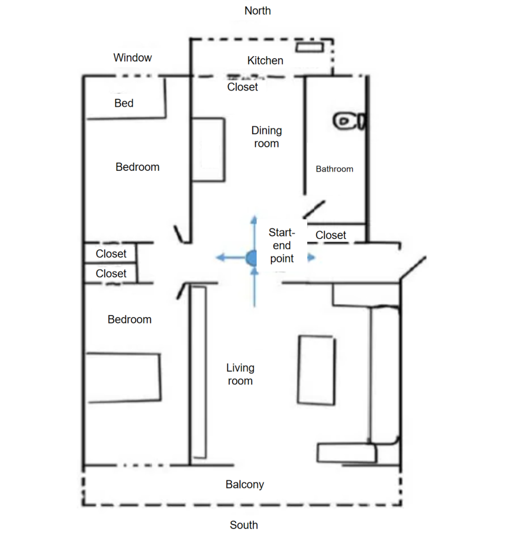
(2) Starting point position selection:
Choose the position for various path possibilities as the starting and ending point of scanning.
(3) Pay attention to scene mutation:
Scene mutation refers to entering another adjacent scene from one scene, or called scene transition. Taking the following figure as an example, the effective LiDAR range can cover the objects in the corridor, but cannot penetrate the point cloud of the inner door and the conference room, so the corridor, front desk and room are three relatively independent scenes.
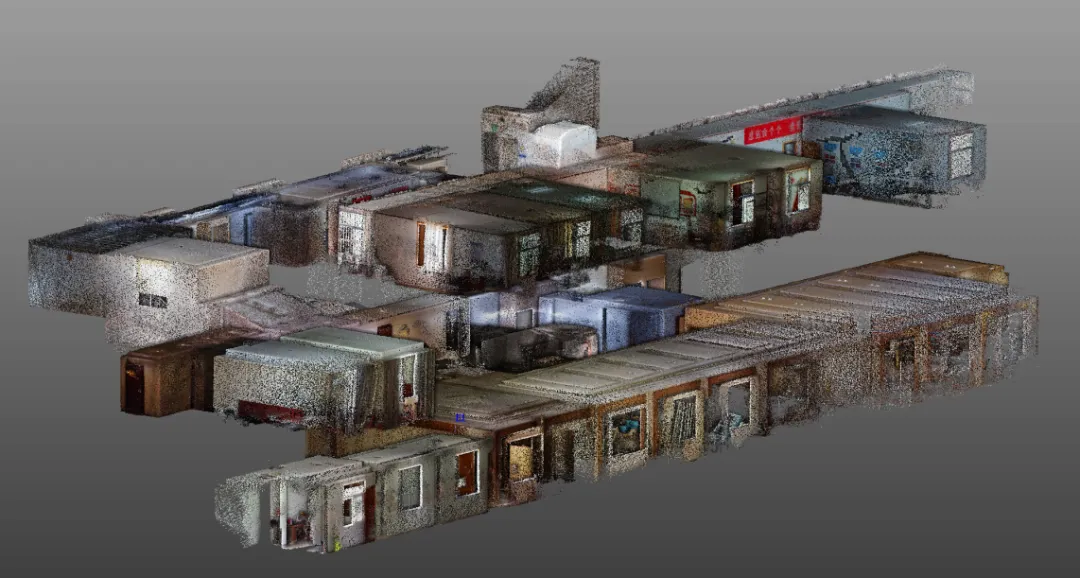
When encountering a sudden scene change, slowly enter the room with a crab step on the side, stay a while to let the LiDAR head get the indoor and outdoor features, and then enter
(4) Walk slowly and avoid rapid turning:
When collecting indoor space, walk slowly, slower than the normal walking speed, avoid large and rapid rotation of the body or sudden stop, etc., resulting in rapid and large deflection and shaking of the equipment, etc., need to have a curvature or U-shaped turn.
(5) Corner and detail scanning:
For multi-rooms environment, the door should be opened in advance, or the scanner should be turned away from the door when scanning, and the door should be opened with the back of the body. Do not move the door when surveying. When passing through the door, stay in front of the door for 5 seconds and scan towards the room to ensure that the features on both sides of the door can be scanned at the same time. Slowly pass through the door sideways, and after the object in the room is scanned, slowly retreat or turn around and leave the room.
Use LixelStudio software to preprocess and post-process the collected point cloud data, such as denoising, registration, etc., to improve data quality.
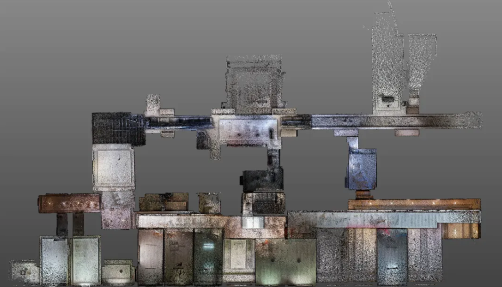
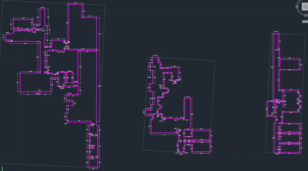
(1) Output the processed point cloud data in .rcp file through and import it into Autodesk CAD.
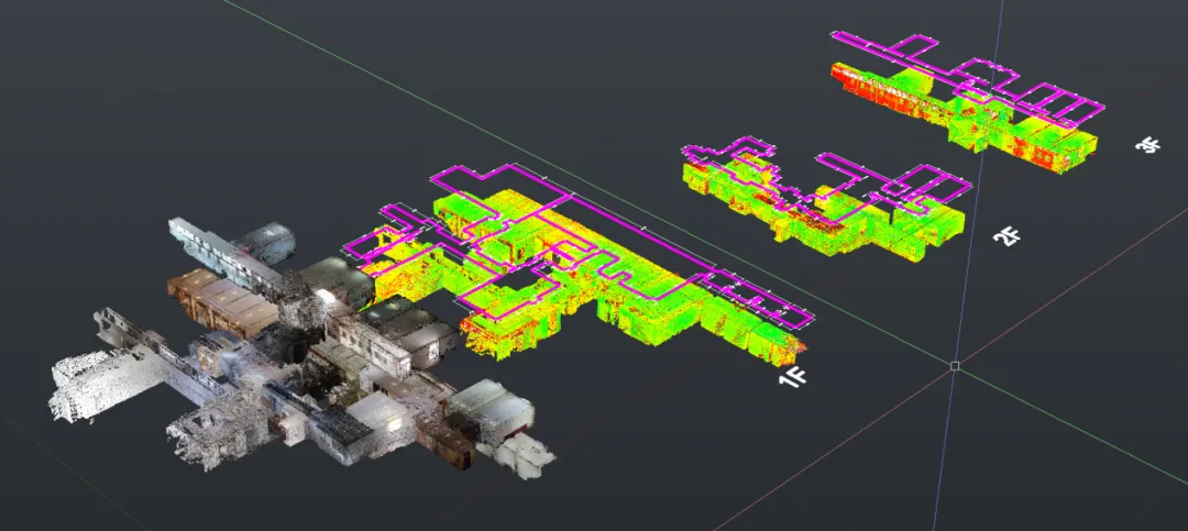
(2) Use the shortcut pointcloudattach command to attach the .rcp to Autodesk CAD. Adjust the appropriate point size and intensity display mode (color scheme is chromatography) in the CAD point cloud module. Based on the point cloud reflection intensity, adjust to the top view and draw the floor plan of the subject.
(3) Click Point Cloud to adjust the point cloud rendering mode. Due to the different materials inside and outside the building, choosing different rendering modes can make the point clouds of different materials appear clearer. Adjusting the transparency of point cloud appropriately can make the contours of walls and other structures clearer. And then you can create layers and draw lines according to the project standards.
(4) To draw a property drawing, you need to turn on the orthogonal command. If the model is not due north or east, draw an xline (extension line) in the top view, use the align command to align the XY axis, then switch to the front view, enter UCS, and align the Z axis with xline + align. After completing the above command, move the point cloud model position to the bottom in the front view to avoid point cloud covering the line drawing.
(5) Finally, use the clipping command to sequentially section the top and bottom of each layer of point cloud model, keep the middle wall line, turn off 3D capture, turn on 2D capture, and draw a 2D floor plan inside the house.
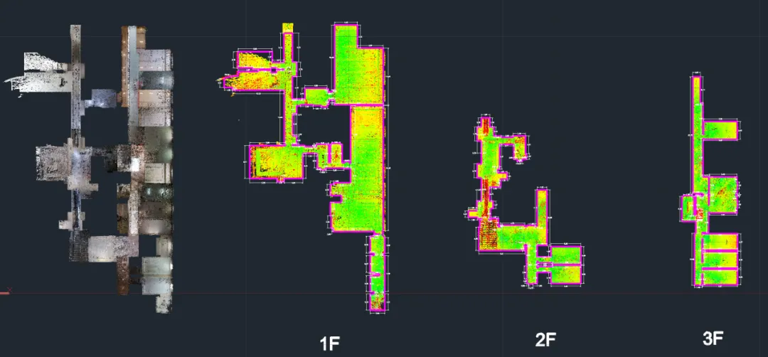
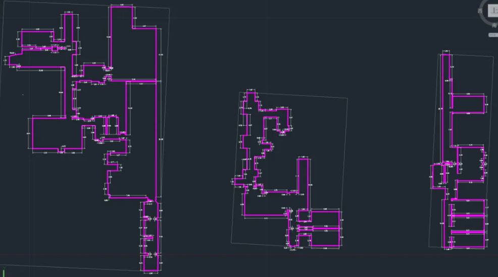
Quantified Results:
By adopting XGRIDS’ Lixel L2 Pro handheld scanner and mapping solution, the client was able to:
Customer Feedback:
“The Lixel L2 Pro handheld 3D scanner has broad application prospects in surveying and mapping scenarios. Its advantages are fast scanning speed, easy portability, and only one operator is needed to complete field work scanning. It can also generate point cloud data with one click, eliminating the need for complex and tedious point cloud splicing work.
At the same time, point cloud post-processing software is highly automated and integrated for workflow of CAD floor plan drawing, and make the results delivered smoothly in a short time.
In addition, the point cloud data collected by the 3D scanner can be viewed at any time, which conveniently and quickly identifies the key problems, avoids the need to return to the field site to re-scan data, and greatly saves rework costs.”
— Guangbin Zhou, surveyor from TBNET
Reality capture let Netflix's Monster scout 35 Italian locations in four days with PortalCam, then plan shots remotely through virtual scouting of 3DGS scans.
.png?x-oss-process=image/resize,w_800/quality,Q_50)
A one-hour Lixel K1 scan of six Culver City blocks gave a generative film pipeline the fixed geometry it needed to keep six locations consistent.
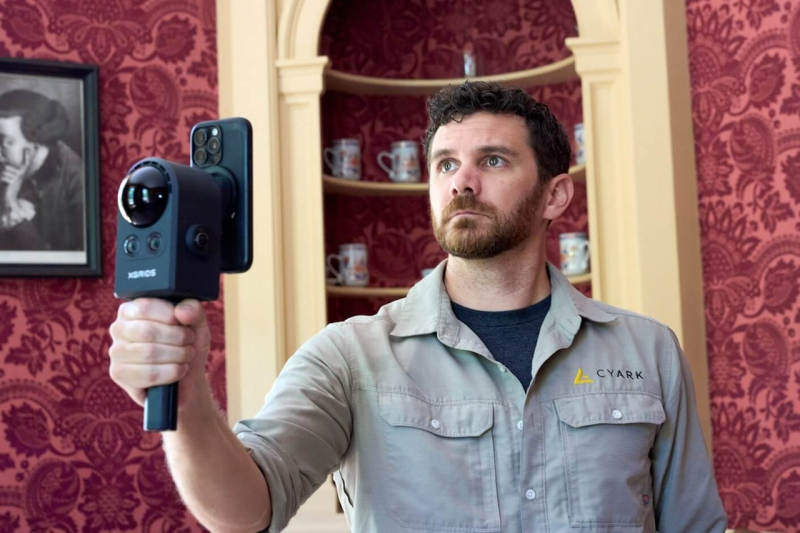
Handheld 3DGS by PortalCam helped CyArk document three landmark interiors for America 250, solving mirror reflections and low-light field challenges.
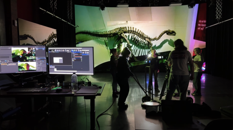
Handheld 3D capture brings real museum spaces to LED volumes, replacing green screens and photogrammetry for fast, cinematic virtual camera moves.